Combining Multiple Probes: A Recipe for Success
Combining measurement techniques enables a wide range of relational characteristics to be measured with just one or two sensors.
#qualitygagingtips

Share
Most types of gaging applications come down to variations of length, usually in one of four basic themes: height, depth, thickness or diameter. Geometric gaging applications are nearly as straightforward, conceptually. Measuring qualities like roundness, straightness, squareness, taper, parallelism or distance between centers is usually a matter of measuring a few dimensional features, then doing some simple calculations.
Better yet, we can let the gage do the calculations. Even simple benchtop gaging amplifiers can simultaneously measure two or more dimensions and manipulate the readings through addition, subtraction or averaging (air gaging is especially useful in this recipe since no other sensor type is small enough to be packed into very small areas). Add a small gaging PC and gaging software, and even the most complex signal sharing and calculations are possible.
Featured Content


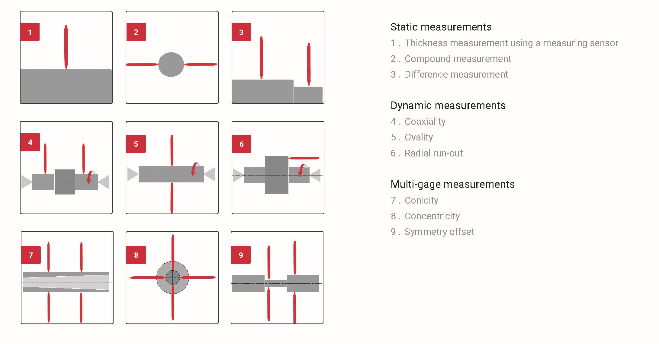
Whether it be linear variable differential transformers (LVDT) or air jets, combining the sensors as seen in the corresponding schematics enables a wide range of relational characteristics to be measured with just one or two sensors. Essentially, it involves setting them up in the proper configuration and polarity and ensuring that the fixture can maintain a precise relationship between the part and the gage heads.
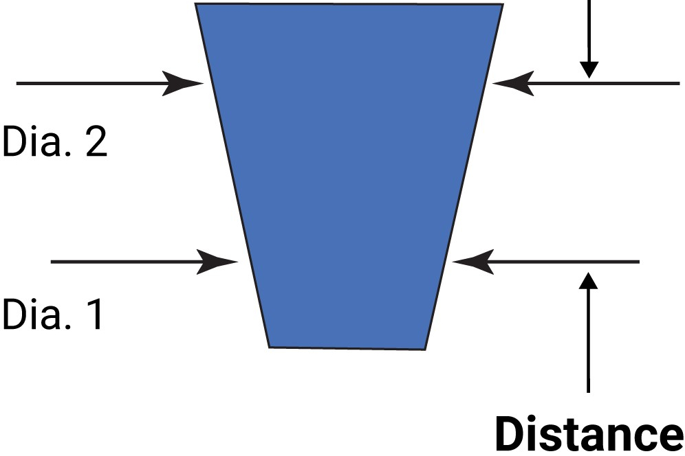
Let’s start with some basic air tooling applications. It’s quite common to have a scenario where one wants to ensure there is no taper condition in the bore. One way to do this is to have a single circuit air plug and tell the operator to explore the bore checking for diameter variation. However, this type of check can be performed much faster and easier for the operator if a two-circuit air plug is used, measuring two diameters independently at two different levels. Then using the two-input, three-readout amplifiers mentioned above, the operator simply inserts the two-circuit plug into the bore, and the display will provide both diameters and the difference (taper condition) simultaneously, with no manipulation required. This same combination is used to measure parts with tapers, such as toolholders, tool spindles or medical implants. However, in this case, rather than a straight bore, the air plug has the same taper as the part being measured. Now the air tool and display will provide the two diameters at the identified location, and by knowing the distance between the two diameters, the actual taper angle can be calculated.
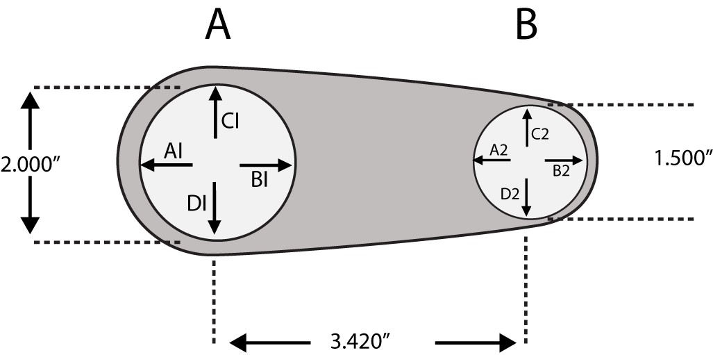
With a little imagination, you can combine several related and/or independent measurements into a single fixture to speed up the gaging process. The figure below shows a fixture gage for measuring connecting rods. Transducers A1 and B1 measure the diameter of the crank bore; out-of-roundness can be checked by comparing that measurement with a second diameter at 90_ (C1 and D1). The same features are measured on the pin bore using transducers A2 through D2. Finally, the distance between bore centers can be calculated using the same gaging data.
Now let’s say we added a second level of the same arrangement of probes. There is now a total of 16 probes, eight on two levels. Using the example above, taper conditions could be made on each bore, along with the part’s calculation bend and twist. Many features are available with the correct formula to combine probes.
Using these principles, machine shops can develop workable fixture gages in-house for a wide range of applications or modify existing gages to add capabilities. Electronic gage heads (such as transducers) and air tooling with multiple jets can be designed in many configurations and sizes, some small enough to permit simultaneous measurements of very closely spaced part features. Before you begin in earnest, you’ll need to check the manufacturer’s specs for gage head dimensions, accuracy and range. Even if you don’t want to build the gage in-house, you can use these ideas to design a “schematic” gage to aid in your discussions with custom gage makers.
RELATED CONTENT
-
You Are Not Spending Enough on Gaging
Is there an intuitive ratio shaping shops’ perceptions of how much gaging capacity is appropriate for their machining capacity? Much has changed; that ratio might need to be reconsidered.
-
Centralization Errors Grow as Bores Get Smaller
It is important to consider the effects of gage centralization when measuring smaller bores. Selecting the right tool is often based on the bore’s size and tolerance.
-
The Many Ways of Measuring Thickness
While it may seem to be a straightforward check, there are many approaches to measuring thickness that are determined by the requirements of the part.

.1692800306885.png)


.1687801407690.png)