Simulation Saves Money When Machining Expensive Parts
Jobs machining expensive materials mean Keselowski Advanced Manufacturing needs to be extremely cautious. The operations manager says Vericut not only prevents mistakes, it shortens cycle times.
#Basics #casestudy

Edited by Evan Doran
Share
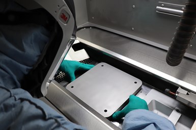
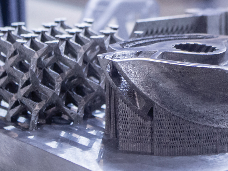
KAM specializes in 3D printed metal parts, both in the printing and the finish-machining stages. These parts are worth tens of thousands of dollars by the time they reach the machines, and thus require careful strategies for machining. Photo Credit: Keselowski Advanced Manufacturing
Since 2018, Keselowski Advanced Manufacturing (KAM) has become a preferred supplier to companies throughout the aerospace and defense, energy, space, automotive and performance motorsports industries.
Representing a new breed of vertically integrated hybrid manufacturing firms, KAM specializes in the design and production of 3D-printed metal parts that are then finish-machined on a fleet of high-end CNC machine tools. It's demanding, difficult work that is compounded by the fact that any mistake can undo weeks of laser bed fusion manufacturing and cost tens of thousands of dollars in material and machine time.
Featured Content


"Unlike machining from billet and bar stock, the parts we're cutting already have considerable value to them,” says James O’Toole, KAM’s operations manager. “Scrap at this point in the manufacturing process could cause serious problems for our customers, never mind the internal expense.”
Simulation provides a way to avoid this expense — but time spent simulating production needs to be recouped elsewhere for efficient cycle times, so KAM also needed software that could perform effective toolpath optimization. According to O’Toole, Vericut from CGTech struck the right balance for KAM.
“Not only does Vericut help us to ensure that the first part is a good part, but it helps us to reduce our setup times, eliminate broken tools and prevent crashes,” O’Toole says.
The Right Software for the Right Job
KAM’s shop floor is home to a variety of Mazak equipment, among them an HCN-5000 horizontal machining center; a Variaxis i-800 five-axis, twin-pallet vertical machining center; a Quick Turn 350MSY turn-mill center; and several Integrex i-300S seven-axis multitasking lathes. The additive side of KAM’s production area also boasts a large array of equipment, with nearly two dozen laser powder bed fusion (LBPF) printers from EOS, SLM Solutions and GE Concept Laser. Some have dual- or quad-laser capabilities, and all are capable of building parts from aluminum, Inconel 625 and 718, titanium Ti64, Haynes 282 superalloy and several other aerospace-grade metals.
Under O’Toole’s supervision, the two departments work very closely with one another and KAM’s design and engineering department. The process plan for any part starts by creating the 3D printing job or “build” in Materialise Magics software, simulating it in Netfabb Ultimate and then releasing it for 3D printing. After thermal processing, the printed job moves to the machining area. It’s here that KAM uses Vericut to simulate the NX-generated part program, checking for gouges, uncut material and collisions.
"We have a very strong programming team, but we're all human, and humans make occasional mistakes," O'Toole says. "While it doesn't happen very often, we've had multiple instances where Vericut has caught errors that would have scrapped a very expensive workpiece.”
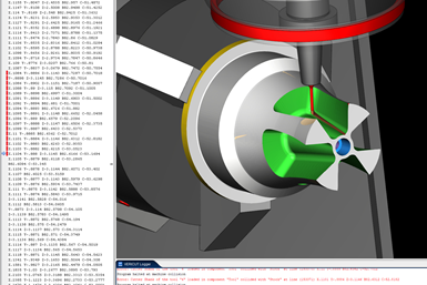
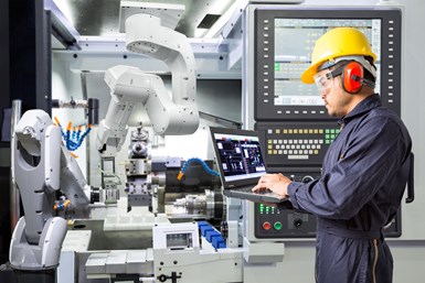
Collisions are disastrous for KAM, so Vericut’s focus on collision avoidance made it especially attractive for the shop. Photo Credit: Keselowski Advanced Manufacturing
Wayfinding Workholding
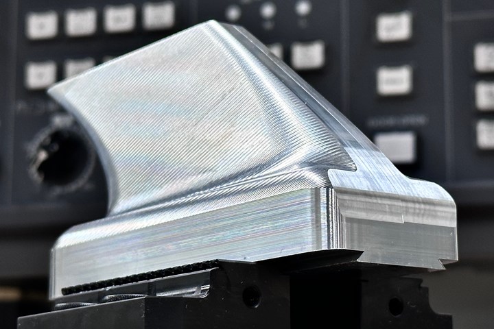
O’Toole noted that one of the more important considerations when machining 3D-printed parts is workholding. Some parts are machined still attached to the build plate, making workholding much easier, but others need to be cut away beforehand. In these instances, determining the best way to fixture what are often thin-walled parts containing complex geometries and freeform surfaces can be quite challenging.
On a traditional billet-made part, operators can determine any subsequent locating features during the first operation, O’Toole says. With additive, the parts don't have those datums defined, even though there are features that must align to them when complete. He compares this to castings and forging, which require finding the “part within the part.”
“You need to strategically look at how you are aligning and then probing the part to make sure that the features you’re machining end up in the right place,” O’Toole says. “We use Vericut here as well, to simulate our probing macros. Not only does it help us to ensure that the first part is a good part, but it helps us to reduce our setup times, eliminate broke tools and prevent crashes.”
RELATED CONTENT
-
Selecting The Right Welder
Many machine shops, on occasion, have a need for welding. It may be for maintenance purposes, repair or to fill the odd contract. This story is a welding process primer for those shops whose main business isn't welding but need to know some basics.
-
Understanding Swiss-Type Machining
Once seen as a specialty machine tool, the CNC Swiss-type is increasingly being used in shops that are full of more conventional CNC machines. For the newcomer to Swiss-type machining, here is what the learning curve is like.
-
6 Steps to Take Before Creating a CNC Program
Any time saved by skipping preparation for programming can be easily lost when the program makes it to the machine. Follow these steps to ensure success.

.1692800306885.png)

.1687801407690.png)