Test Indicators Excel for Tight Tolerances and Small Spaces
Test indicators are sometimes overlooked or replaced by dial or digital indicators, but for some situations, they can’t be beat.
#qualitygagingtips

Share
Test indicators are pretty distinct from dial indicators. The obvious difference is that test indicators have lever-type contacts, and they tend to be smaller and lighter.

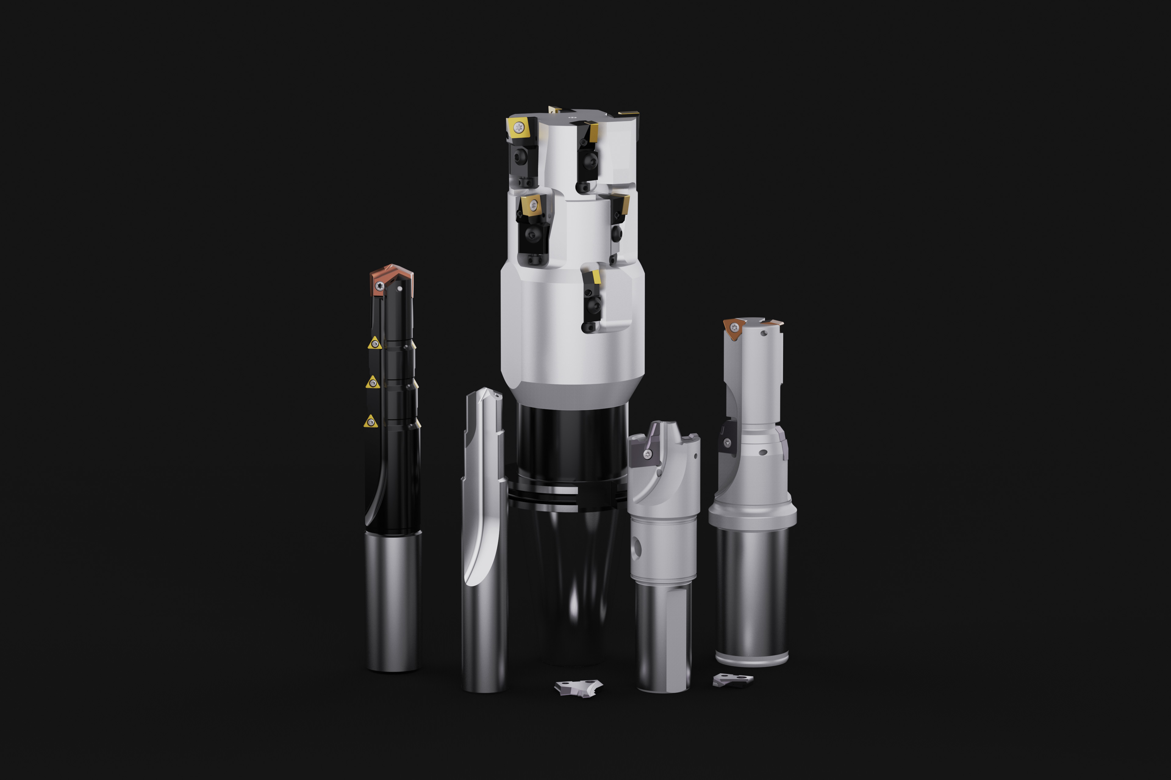
Application examples for test indicators. Photo credit: George Schuetz
Test indicators excel at consistency measurements, as opposed to comparative ones. For surface-plate layout work or inspection, they are used most often to explore relatively broad part surfaces in either one or two dimensions; for example, measuring variations in height, flatness or roundness. Test indicators are often used in combination with a height stand and a surface plate, and either the workpiece or the stand can be moved around freely on the plate. When combined with a V-block or a pair of centers, test indicators can be used to test for roundness or runout on cylindrical parts. The angular motion of the test indicator's lever enables the contact to ride easily over irregularities on part surfaces.
Featured Content


This ability to ride over irregular surfaces also makes test indicators well-suited for use in machine setups — particularly on lathes. The indicator is held by an articulated test stand that is usually mounted right on the machine. The operator brings the indicator into rough contact with the chucked blank, then turns the spindle to obtain a very quick reading on runout. No mastering is required when checking roundness, runout or flatness. The user simply brings the indicator close to the part surface, pushes down on the lever to make contact with the part and rotates the indicator's bezel to zero. It's far quicker than the typical setup for a dial indicator. Even though indicator manufacturers often provide a small or large dial test indicator, they tend to be relatively small and visibility may be limited, especially within the machine checking.
Test indicators can be oriented relative to the workpiece and at a wide range of approach angles. The narrow lever and small contact ball also fit readily into many places that are unreachable by other means. However, there is a note of caution to be considered when using the test indicator. Cosine error is most typically seen with test-style indicators. With a test-style indicator, accuracy is greatest when the axis of the contact point is perpendicular to the measuring direction. This is seldom the case, however, and as the angle of the contact to the surface increases, the amount of vertical distance encompassed (change in height) also increases. The result is cosine error. Tables can be used to correct for this error as follows, where A is the angle between the probe and the surface of the part:
| Angle A | Correction Factor |
| 5° | 0.996 |
| 10° | 0.985 |
| 15° | 0.965 |
| 20° | 0.940 |
| 30° | 0.866 |
In general, the rule is to always try to maintain the probe angle to within ±15º in either direction.
Just like other analog tools, test indicators have generally higher resolution with a shorter range of measurement. Typical resolution (least grad) is 0.0001" to 0.00005" for test indicators; for dial indicators, it is 0.001" to 0.0001". The measurement range of test indicators is usually between 0.008" and 0.030".
Because of their short range, test indicators enable just a single revolution of the pointer around the dial. Therefore, the test indicator truly acts as a dial comparator as there is little chance of missing a revolution of the hand and making a bad reading. Test indicator pointers always travel clockwise, and the dials are continuously reading — meaning the numbers keep ascending until the dial comes back to zero.
Test indicators are extremely useful little items that are sometimes overlooked or replaced by dial or digital indicators. However, for some small locations or tight tolerances, they can’t be beat.
RELATED CONTENT
-
Gaging Countersunk And Chamfered Holes
While countersunk and chamfered holes are similar in appearance, functionally they are quite different. Consequently, different gages exist to serve these different functional requirements.
-
Composites Machining for the F-35
Lockheed Martin’s precision machining of composite skin sections for the F-35 provides part of the reason why this plane saves money for U.S. taxpayers. That machining makes the plane compelling in ways that have led other countries to take up some of the cost. Here is a look at a high-value, highly engineered machining process for the Joint Strike Fighter aircraft.
-
A Case for Combining Workholding with Optical Scanning
Automotive dies and die inserts are often complex, one-off parts with little room for error. Integrity Tool's investments in modular workholding tools and 3D optical scanning have allowed the company to create niche capabilities for its CNC machined parts.

.1692800306885.png)


.1687801407690.png)