The Impact of Cutting Teeth Spacing on Machining Stability
Many cutter designs are available, and variable teeth spacing (or variable pitch) cutters can be used to influence milling stability. Let’s discuss why teeth spacing affects stability.
Share
Traditional end mill designs select equal spacing between the teeth. With four teeth, for example, the angle between each tooth is 90 degrees. This equal spacing is also called constant pitch. As an alternative, it is possible to apply unequal teeth spacing. Today’s cutting tool manufacturers offer many options with this unequal spacing. The motivation for these alternate designs is often reduced potential for chatter, a self-excited vibration that can occur in milling and, therefore, increased metal removal rates. Varying the helix angle from tooth to tooth has also been implemented to reduce chatter, but we will focus on variable teeth spacing.
Because the tool-toolholder-spindle-machine combination is not rigid, when the cutting force is applied to the tool during milling, vibration occurs. The two types of vibration seen during milling are forced vibration and self-excited vibration. In forced vibration, the cutting force and corresponding vibration repeat from one tooth to the next. This gives the consistent surface finish that is required in production.
Featured Content


In self-excited vibration, on the other hand, the force and vibration do not repeat from one tooth to the next. This causes the chip thickness to vary from one tooth to the next. The variable chip thickness leads to a variable force which, in turn, affects the current vibration. We call this “regeneration of waviness.” This is a feedback mechanism similar to the rotary encoder attached to the motor that drives the ball screw to move the CNC machine’s table. The current position (from the encoder) is compared to the commanded position (in the part program) and the motor turns the ball screw until they match.
In milling, the regeneration of waviness feedback can cause the process to become unstable, which is referred to as chatter. Whether we obtain forced vibration (good surface finish) or chatter (poor surface finish) depends on several factors. These include the spindle speed, radial depth of cut, axial depth of cut, vibration response of the tool-toolholder-spindle-machine (and sometimes the workpiece) and, of course, the tool geometry. The reason that variable teeth spacing affects chatter is that the unequally spaced teeth tend to interrupt regeneration of waviness. With unequal teeth spacing, the individual teeth arrive at the cut with different intervals and the normal timing of surface generation is modified. The outcome is a change in stability behavior.
Let’s consider an example for an end mill with four teeth. With equal teeth spacing, the angles of the individual teeth are 0, 90, 180 and 270 degrees. Consider variable tooth spacing as shown in the top left panel of the figure, where the tool rotation is clockwise and the feed direction is to the right. The teeth angles are 0 (tooth 1), 95 (tooth 2), 180 (tooth 3) and 275 (tooth 4) degrees. Teeth 2 and 4 are advanced by 5 degrees (95 and 275 degrees), while teeth 1 and 3 are located at their normal angles (0 and 180 degrees).
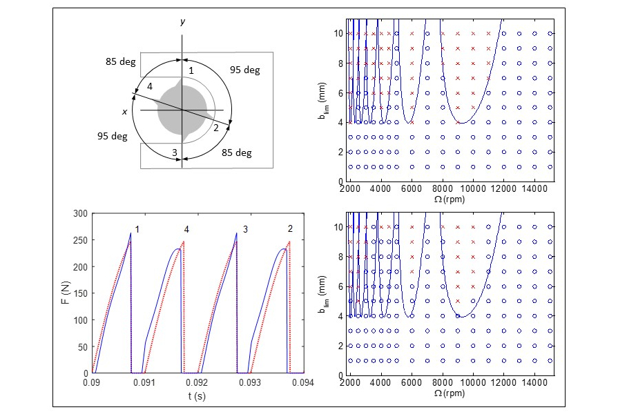
The bottom left panel shows the cutting force (F) versus time (t) for the variable (blue) and equal (red) teeth spacing options. The cutting conditions are 30% radial immersion up (conventional) milling, 3-mm axial depth, 0.15-mm feed per tooth and 15,000-rpm spindle speed. Notice that the variable spacing causes the amount of material removed by each tooth to vary and, therefore, the cutting force. The force for teeth 1 and 3 is higher for the variable spacing (blue) than the equal spacing (red), while the force for teeth 2 and 4 is lower for the variable spacing than the equal spacing. The time interval from tooth 1 to 4 is smaller than the time interval from tooth 4 to 3 for the variable spacing. This is because there is 85 degrees between teeth 1 and 4, but there is 95 degrees between teeth 4 and 3.
The right column in the figure shows the effect on stability. The top panel is for equal teeth spacing, where the vertical axis is axial depth of cut and the horizontal axis is spindle speed. The blue line gives the stability boundary (below the boundary is stable and above the boundary is chatter). The blue circles identify stable spindle speed-axial depth combinations and the red crosses identify chatter. The bottom panel displays the same stability boundary (equal teeth spacing), but now the blue circles and red crosses are for the variable teeth spacing. The stability limit is increased for many spindle speed-axial depth combinations, but stable and unstable zones remain.
To conclude this discussion, we also need to discuss the feed. As shown in the force versus time plot, the chip thickness from one tooth to the next is different for the unequal teeth spacing. It is, in fact, larger for some teeth than it would be if the teeth were equally spaced. This means that we should reduce the feed per tooth when using a variable pitch end mill if we don’t want the force to be larger on any tooth than it would have been for an equal pitch design.
RELATED CONTENT
-
A Spiral Milling Custom Macro Using Constant Contouring Feedrate
Helical milling or “spiral” milling are helpful when machining a circular pocket that is much larger than the milling cutter diameter.
-
6 Machine Shop Essentials to Stay Competitive
If you want to streamline production and be competitive in the industry, you will need far more than a standard three-axis CNC mill or two-axis CNC lathe and a few measuring tools.
-
Bringing Machining In-House to Keep up With Demand for Offroading Parts
This company brought its machining processes in-house to meet annual increases in demand, utilizing CAMWorks’ multi-axis milling solutions to boost production, shorten delivery times and support growth.

.1692800306885.png)


.1687801407690.png)